
The following shows how to control USB HostSlave IP Core with simple software driver.
USB Host Core Initial Configuration
Connecting the game pad and turning the USB bus in Bus Reset mode, USB slave device (game pad) goes in Default State. Then USB HostSlave IP Core connection event is sent to the CPU as an interrupt signal (CONNECTION_EVENT) . The USB slave device in this state accepts transactions for default address(0).
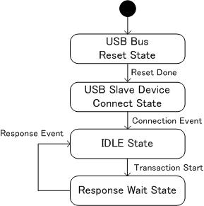
Process to Default State
Data Transfer between USB Host and Slave
USB Host Core and USB slave device communicate with IN, OUT, SETUP transaction.
OUT Transaction
OUT Transaction is used to send data from USB Host to USB Slave. The transaction starts in the following steps.
- Setting HOST_TX_TRANS_REG register’s TRANSACTION_TYPE field as OUTDATA0_TRANS or OUTDATA1_TRANS
- Setting send data to USB_TX_FIFO_DATA
- Setting HOST_TX_CONTROL_REG register’s TRANS_REQ_BIT field as 1
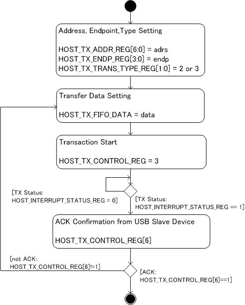
OUT Transaction Flow
IN Transaction
In Transaction is used to receive data from USB Slave Device to USB Host. The transaction starts in the following steps.
- Setting HOST_TX_TRANS_REG register’s TRANSACTION_TYPE as IN_TRANS
- Setting HOST_TX_CONTROL_REG register’s TRANS_REQ_BIT field as 1
- Waiting USB_INTERRUPT_STATUS_REG register’s TRANS_DONE_BIT field turns to 1
- Reading USB_RX_FIFO_DATA_COUNT_LSB to know the number of received bytes
- Reading USB_RX_FIFO_DATA register same count as SB_RX_FIFO_DATA_COUNT_LSB
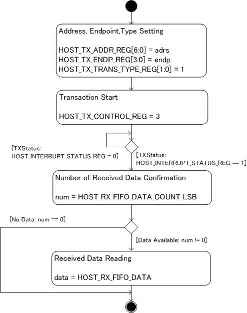
IN Transaction Flow
SETUP Transaction
Setup transaction is used in Control Transfer. SETUP transaction transmits information to the USB device. The transaction starts in the following steps.
- Setting HOST_TX_TRANS_REG register’s TRANSACTION_TYPE as SETUP_TRANS
- Setting device request data to USB_TX_FIFO_DATA register
- Setting HOST_TX_CONTROL_REG register’s TRANS_REQ_BIT field as 1
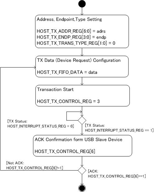
SETUP Transaction Flow
Getting Descriptors
The standard USB descriptors contain information about what kind of device is connected to the connector.
- Device Descriptor
- Configuration Descriptor
- Interface Descriptor
- HID Descriptor
- Endpoint Descriptor
These descriptors are provided by the device in response to control transfer. HID(Human Interface Device) descriptor is a class specific descriptor and only available in HID class device.
Detailed descriptions of each descriptor…
From the descriptors, it appears that the game pad has in the following features.
- The number of configurations is 1
- The number of interfaces is 1
- The number of endpoints is 1(except endpoint0)
- Interface class is 33(HID)
- Endpoint address is 1
- The type of endpoint 1 is Interrupt IN transfer
- Maximum packet size of endpoint 1 is 4
Interrupt Transfer
The descriptors of the game pad specify that the data is transferred by Interrupt transfer to endpoint 1. Interrupt transfer starts at regular intervals which is generated by timer functionality of the CPU. the game pad returns pad information at that time in response to the interrupt transfer.
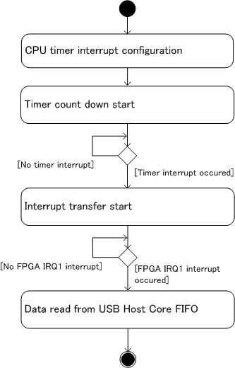
Interrupt Transfer Flow
Getting Game Pad Data
The pad information(which button is pushed, which button is released) is stored in the returned data of interrupt transfer. The game pad in this case returned pad status as 4 bytes data. The bit position of each button is obtained by HID class REPORT descriptor.
| Byte | Field | Description |
|---|---|---|
| 0 | x Arrow Key | Left: 0 Center:0x7f, Right: 0xff |
| 1 | y Arrow Key | Up: 0 Center:0x7f, Down: 0xff |
| 3 | Button Group0 | 8 buttons status are assigned to each bit of 8bits OFF:0, ON:1 |
| 4 | Button Group1 | 2 buttons status are assigned to bit0 and bit1 of 8bits OFF:0, ON:1 |
Test Program
This is a simple program for testing the implementation.
- USB device address is 5
- Interrupt transfer is issued every 1 second by CPU timer interrupt
- USB Host Core FIFO is read at IRQ1 from FPGA, then the data is stored in game pad data struct
Program (excerpt)
Main
 int main(void){
     int i;
     char buf[64];

     puts ("USB Test\n");

     intr_disable();
     int_config();
     timer1_config(); // Timer configuration for Interrupt transfer
     intr_enable();

     usb_init(); // USB Host Core initialization

     while(1) {
         //Interrupt transfer is invoked in interrupt handler
     }
     return 0;
 }
Timer configuration
void timer1_config() {
     // TMU1 is configured to generated the interrupt every one second
     // pck = 33MHz = 30ns, pck/1024 = 32.5KHz = 30us
     TMU.TSTR0.BYTE = 0x00; // stop timer
     // set interrupt priority for TMU0(bit28:24),TMU1(bit20:16)
     INTC.INT2PRI0.LONG = 0x0c0c0000; // bit 28-24 (0,1 = mask)
     INTC.INT2MSKCR.LONG = 1; // TMU0-2
     TMU1.TCOR = get_timer_count(1000000000); // timer constant (1s)
     TMU1.TCNT = get_timer_count(1000000000);
     TMU1.TCR.WORD = 0x0024; // timer control UNF=0,UNIE=1,CKEG=00 TPSC=100
     TMU.TSTR0.BYTE = 0x02; // start tmu1
 }
Interrupt handler(Timer interrupt)
 void INT_TMU1_TUNI1() {
     unsigned int x;
     puts ("TMU1 INT\r\n");
     // clear TCR0.UNF
     TMU1.TCR.WORD = TMU1.TCR.WORD & ~0x0100;
     x = 1;
     while (x) x = INTC.INT2A0.LONG & 1; // bit0 : TMU0-2
     // start usb interrupt transfer
     if (usb_state == USB_NORMAL) interrupt_in_transfer_nb(5, 1); // Interrupt transfer to address5, endpoint1
 }

 void interrupt_in_transfer_nb(int adrs, int endp) {
     USB_TX_ADDR_REG.LONG = adrs;
     USB_TX_ENDP_REG.LONG = endp;
     USB_TX_TRANS_TYPE_REG.LONG = 1; // IN TRANS
     int_trans_done = 0;
     USB_CONTROL_REG.LONG = 1;
     puts("Start INT_TRANS\r\n");
 }
Interrupt handler (FPGA IRQ1interrupt)
void INT_IRL_LEVEL11() {
     // INTR IRQ1
     unsigned int d;
     char buf[64];
     d = USB_INTERRUPT_STATUS_REG.LONG;
     puts("INT detected\r\n");
     if (d & 0x1) {
         puts("TRANS_DONE_BIT\r\n");
         USB_INTERRUPT_STATUS_REG.LONG = 1; // clear status
         int_trans_done = 1;
         if (usb_state == USB_NORMAL) interrupt_in_transfer_get(5, 1); // Get data from USB Host Core
     } else if (d & 0x2) {
         puts("RESUME_INT_BIT\r\n");
         USB_INTERRUPT_STATUS_REG.LONG = 2;
     } else if (d & 0x4) {
         puts("CONNECTION_EVENT_BIT\r\n");
         USB_INTERRUPT_STATUS_REG.LONG = 4;
         int_connect_done = 1;
     } else if (d & 0x8){
         puts("SOF_SENT_BIT\r\n");
         USB_INTERRUPT_STATUS_REG.LONG = 8;
     } else {
         sprintf(buf, "UNKOWN INT %x \r\n", d);
         puts(buf);
     }
 }

 void interrupt_in_transfer_get(int adrs, int endp) {
     int i, fnum;
     char buf[64];
     unsigned int status;

     // buffer clear
     for (i=0; i < 4; i++) joypad_status.PACKED[i] = 0;
     while (!int_trans_done) ;
     puts("interrupt in trans done\r\n");

     status = USB_RX_STATUS_REG.LONG;
     sprintf(buf, "INT RX STATUS %x \r\n", status);
     puts(buf);
     // get IN data
     fnum = USB_RX_FIFO_DATA_COUNT_LSB.LONG;
     sprintf(buf,"interrupt in length = %d\r\n",fnum);
     puts(buf);
     for (i = 0; i < fnum; i++) {
         // Read recieved data and store them in joypad_status struct
         if (i <4) joypad_status.PACKED[i] = USB_RX_FIFO_DATA.LONG;     }
     // status
     sprintf(buf, "X = %x\r\n",joypad_status.BYTE.x);
     puts(buf);
     sprintf(buf, "Y = %x\r\n",joypad_status.BYTE.y);
     puts(buf);
     sprintf(buf, "B1 = %x, %d %d\r\n",joypad_status.BYTE.b1.BYTE,
     joypad_status.BYTE.b1.BIT.button0,
     joypad_status.BYTE.b1.BIT.button1);
     puts(buf);
     sprintf(buf, "B1 = %x, %d %d %d %d %d %d %d %d\r\n",joypad_status.BYTE.b0.BYTE,
         joypad_status.BYTE.b0.BIT.button0,
         joypad_status.BYTE.b0.BIT.button1,
         joypad_status.BYTE.b0.BIT.button2,
         joypad_status.BYTE.b0.BIT.button3,
         joypad_status.BYTE.b0.BIT.button4,
         joypad_status.BYTE.b0.BIT.button5,
         joypad_status.BYTE.b0.BIT.button6,
         joypad_status.BYTE.b0.BIT.button7);
     puts(buf);

 }
Game pad data struct
typedef union {
     unsigned char PACKED[4];
     struct {
         unsigned char x; // left: 0, center:0x7f. right: 0xff
         unsigned char y; // up: 0, center:0x7f. down: 0xff
         union {
             unsigned char BYTE;
             struct {
                 unsigned char button0 : 1;
                 unsigned char button1 : 1;
                 unsigned char button2 : 1;
                 unsigned char button3 : 1;
                 unsigned char button4 : 1;
                 unsigned char button5 : 1;
                 unsigned char button6 : 1;
                 unsigned char button7 : 1;
             } BIT;
         } b0;
         union {
             unsigned char BYTE;
             struct {
                 unsigned char button0 : 1;
                 unsigned char button1 : 1;
                 unsigned char : 6;
             } BIT;
         } b1;
     } BYTE;
 } st_joypad;