
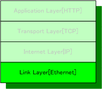
Internet Protocol Suite
The software driver implements low-level API to handle Ethernet Frame transfer between the Link Layer and the Internet Layer.
API Specification
Ethernet Frame Transmission
void ether_write_frame(int flen,unsigned char *fbuf);
- Description
- The function copies the number of bytes specified by flen from fbuf to Local Memory in the FPGA, and send it as an Ethernet Frame.
- Return Value
- None
Ethernet Frame Reception
int ether_read_frame(unsigned char *fbuf);
- Description
- The function stores received Ethernet Frame from Local Memory in the FPGA to fbuf.
- Return Value
- The function returns the number of bytes of received Ethernet Frame on success.
Ethernet Frame Transmission Flow
An Ethernet Frame is transmitted in the following way.
- Copies Frame data from CPU main memory to FPGA Local Memory
- Set Mode Register TXEN bit of MAC Core to 1
- Set Local Memory address which the data stored in to TXPNT of Tx Buffer Descriptor register in MAC Core.
- Set Tx Buffer Descriptor RD bit of MAC Core to 1.
- Wait for transmit complete interrupt.
- Clear the interrupt.
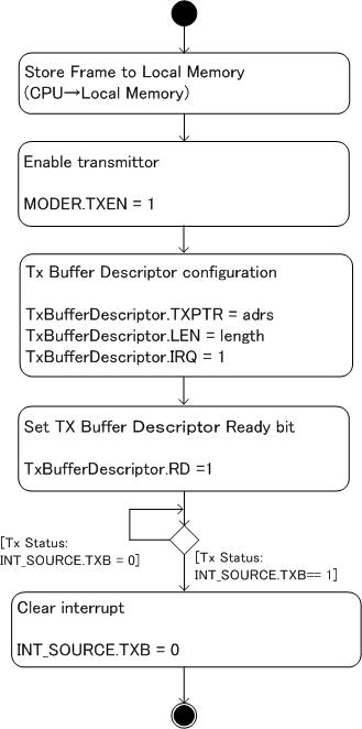
Ethernet Frame Transmit Flow Chart
Frame CRC will be calculated and added to the end of the Frame. After Tx Buffer Descriptor is enabled, Ethernet MAC Core reads data from Local Memory then send it to PHY as an Ethernet Frame.
Transmission API Implementation – ether_write_frame()
 void ether_write_frame(int flen,unsigned char *fbuf) {
     int i, flush;
     struct st_txdesc_l txl;
     unsigned int a;
     // Tx Buffer Descriptor configuration
     txl.LONG = 0;
     txl.IRQ = 1; // Interrupt Request Enable
     txl.PAD = 1; // PAD Enable
     txl.CRC = 1; // CRC Enable
     txl.WR = 1; // Wrap
     // Store Frame to Local Memory in FPGA
     a = ETHER_BUF_TX_BASE;
     for (i=0; i< flen;i++) {
         if (((a+i) % 4) == 3) flush = 1;
         else flush = 0;
         if (i == (flen -1)) flush = 1; // final data
         ether_write_byte(a+i, fbuf[i], flush);
     }

     // set Tx Buffer Descriptor ready bit
     txl.RD = 1;
     (*(volatile unsigned int *)(ETHER_BD_BASE)) = txl.LONG;
 }
Ethernet Frame Reception Flow
An Ethernet Frame is received in the following way.
- Set Mode Register RXEN bit of MAC Core to 1
- Set Local Memory address, which specifies the data to be received to RXPNT of Rx Buffer Descriptor in MAC Core.
- Set Rx Buffer Descriptor E bit of MAC Core to 1.
- Wait for reception complete interrupt.
- Clear the interrupt.
- Copies Frame data from FPGA Local Memory to CPU main memory.
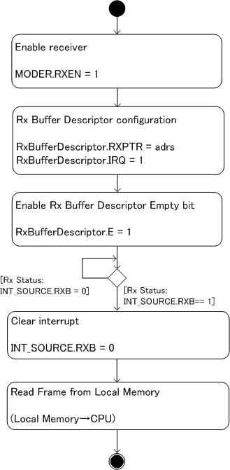
Ethernet Frame Reception Flow Chart
The Frame data from PHY is transferred from Ethernet MAC Core to Local Memory according to the configuration of Rx Buffer Descriptor register. CRC in the Frame is removed and not stored in Local Memory.
Reception API Implementation – ether_read_frame()
 int ether_read_frame(unsigned char *fbuf) {
     int i,j,p, size,s;
     unsigned int x;
     struct st_rxdesc_l rxl;

     // Read byte data from FPGA to CPU
     rxl.LONG = (*(volatile unsigned int *)(ETHER_BD_RX_BASE+ether_cur_rx_bd*8));
     size = rxl.LEN; // byte size
     p =0;
     s = size /4;
     if ((size %4 ) != 0) s++;
     for (i = 0; i< s; i++) {
     x =(*(volatile unsigned int *)(ETHER_BUF_RX_BASE+ether_cur_rx_bd*ETHER_BUFFER_SIZE+i*4));
     for (j=0;j <4; j++) {
         fbuf[p] = (x > (3-j)*8)&0xff; // copy each byte
         p++;
     }
     }
     // set Rx Buffer Descriptor empty bit
     rxl.LEN = 0;
     rxl.E = 1;

     (*(volatile unsigned int *)(ETHER_BD_RX_BASE+ether_cur_rx_bd*8)) = rxl.LONG;

     if (ether_cur_rx_bd == (ETHER_MAX_RX_BD-1))
         ether_cur_rx_bd = 0;
     else
         ether_cur_rx_bd++;

     return size;
 }