
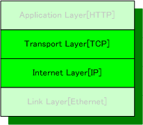
Internet Protocol Suite
The implementation for TCP/IP uses uIP*1 as a TCP/IP Stack.
uIP
uIP is an open source TCP/IP Stack developed by Adam Dunkels of the Networked Embedded Systems group at the Swedish Institute of Computer Science . The IP is free for both commercial and non-commercial use. uIP is written in C language and very small code size, very low RAM usage TCP/IP Stack. It also Includes a set of example applications: web server, web client, Telnet server,etc.
uIP contains in the following directories.
uip-1.0
         uip/
         apps/
             webserver/
         doc/
         lib/
         unix/
TCP/IP Stack source code is in uip directory, and WEB Server example application is in app/webserver directory respectively. These two directories are used to implement TCP/IP Stack and WEB Server.
uIP Configuration
To fit uIP to the target system, configuration setting and timer implementation is required.
Configuration File Setting
Most configuration parameters to be modified is in the file “uip-conf.h”. The main modification points are data types and array size. The array size decides the packet’s buffer size and it also affects MSS (Maximum Segment Size).
#ifndef __UIP_CONF_H__
 #define __UIP_CONF_H__

 // Data type definitions
 typedef unsigned char u8_t;
 typedef unsigned short u16_t;
 typedef unsigned short uip_stats_t;
 //
 #define UIP_CONF_MAX_CONNECTIONS 40 // Maximum number of TCP connections
 #define UIP_CONF_MAX_LISTENPORTS 40 // Maximum number of listening TCP ports
 #define UIP_CONF_BUFFER_SIZE 840 // uIP buffer size

 #define UIP_CONF_BYTE_ORDER LITTLE_ENDIAN
 #define UIP_CONF_UDP 0
 #define UIP_CONF_UDP_CHECKSUMS  1
 #define UIP_CONF_STATISTICS 1
 // web server header file
 #include "webserver.h"
 #endif // __UIP_CONF_H__
Timer Implementation
The timer is used to change the TCP/IP connection state from TIME_WAIT to CLOSED, and for re-transmit timing of the packet to be sending. In this implementation, 32bits timer unit in SH-4A (TMU2) is used for the timer function. In the following configuration, TMU2 generates an under-flow timer interrupt every 1 second.
(clock-arch.h)
#ifndef __CLOCK_ARCH_H__
 #define __CLOCK_ARCH_H__

 typedef unsigned int clock_time_t;
 #define CLOCK_CONF_SECOND 1000

 int get_timer_count_ether(int ms_count);

 #endif // __CLOCK_ARCH_H__
(clock-arch.c)
#include "iodefine.h"
 #include "clock-arch.h"

 clock_time_t
 clock_time(void) {
     // return TMU2 current counter
     unsigned int x = TMU2.TCNT;
     return x;
 }

 int get_timer_count_ether(int ms_count) {
     return (int)((float)ms_count/0.030720); // 30ns x 1024 (PCK/1024)
 }

 void clock_init(void) {
     // TMU2 is used for Networking
     // Configured to count ARP timeout
     // pck = 33MHz = 30ns, pck/1024 = 130KHz = 30us
     // set interrupt priority for TMU0(bit28:24),TMU1(bit20:16), TMU2(bit12:8)
     INTC.INT2PRI0.LONG = 0x0c0c0c00; // bit 28-24 (0,1 = mask)
     INTC.INT2MSKCR.LONG = 1; // TMU0-2
     TMU2.TCOR = get_timer_count_ether( 1000); // 1Sec
     TMU2.TCNT = get_timer_count_ether( 1000);
     TMU2.TCR.WORD = 0x0024; // timer control UNF=0,UNIE=1(int),CKEG=00 TPSC=100
 }
uIP Porting to the Target System
An Ethernet Frame is received, uIP starts data processing. The first step is to check the type field in the Frame, then the process is branched depending on the type value.If the Frame is ARP packet, uip_arp_arpin() is called to prepare ARP response packet. The ARP response packet is set the target embedded system’s MAC address as a source address. The ARP packet is transmitted by calling ether_write_frame().
If the Frame is IP packet, the data is processed in the following way.
- uip_arp_ipin() is called to update internal ARP table. This update confirms that a pair of source IP address and MAC address in current table has same value in the IP packet.
- uip_input() is called to start TCP packet processing. Depending on current TCP state, event flag is checked and then UIP_APP_CALL() is called. WEB Server application is handled in UIP_APP_CALL().
- After calling UIP_APP_CALL(), if there is an IP packet for transmission, uip_arp_out() is called to generate Ethernet Header data.
- ether_write_frame() is called to transmit Ethernet Frame.
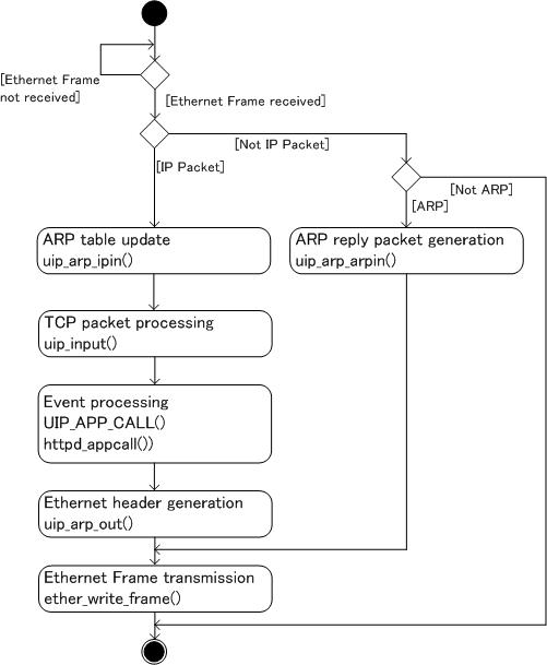
uIP Processing Flow Chart
Actual coding is below. In the source code, uip_len and uip_buf are global variables defined in uIP. The variables are used for sharing data between uIP(TCP/IP) and Ethernet. uip_buf stores transmission/reception packet and uip_len stores effective data length in uip_buf.
(SH4 interrupt handler INTR IRQ2)
  void INT_IRL_LEVEL9() {
     // INTR IRQ2
     struct st_intsrc int_src;
     int i;
     int_src.LONG = ETHER_INT_SOURCE.LONG;

     if (int_src.TXB) {
         ETHER_INT_SOURCE.LONG = 1; // Clear Int
     }
     if (int_src.RXB) {
         // Ether packet is received
         ETHER_INT_SOURCE.LONG = 4; // Clear Int

         uip_len = ether_read_frame(uip_buf);
         // Outgoing packet
         if(uip_len > 0) {
             if(BUF->type == htons(UIP_ETHTYPE_IP)) {
                 // IP Packet
                 uip_arp_ipin();
                 uip_input();
                 if(uip_len > 0) {
                     uip_arp_out();
                     ether_write_frame(uip_len, uip_buf);
                 }
             } else if(BUF->type == htons(UIP_ETHTYPE_ARP)) {
                 // ARP
                 uip_arp_arpin(); // uip_len will be 42 (frame(14)+arp packet(28))
                 if(uip_len > 0) {
                     ether_write_frame(uip_len,uip_buf);
                 }
             }
         }
     }
 }