ModelSimコマンドライン実行用シェルスクリプトのサンプル・データを使って、Verilog-HDLとVHDLの記述を比較しました。このサンプル・データは、シミュレータの実行スクリプトの動作確認を目的としているため、設計データは次のように非常に単純です。
設計データの概要
- トップ・モジュールはmod_top
- mod_top内部は2つのモジュールmod_aとmod_bで構成される。
- mod_aとmod_bは直列に接続され、パイプラインを構成する。
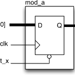
- mod_a内部は8ビットの非同期リセット付きレジスタ。入力がそのまま出力される。
- mod_a内部は8ビットの非同期リセット付きレジスタ。入力の反転が出力される。
構成モジュール
トップ・モジュール: mod_top
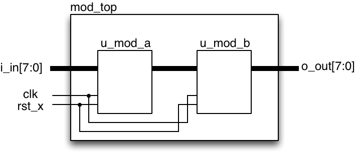
mod_topモジュール
サブ・モジュール: mod_a

mod_aモジュール
サブ・モジュール: mod_b
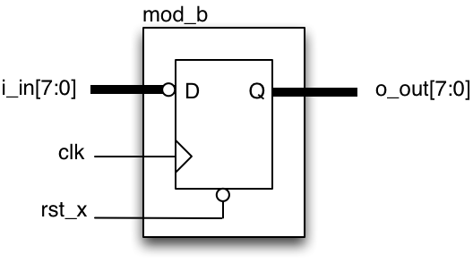
mod_bモジュール
記述比較
サブ・モジュール:mod_a
Verilog-HDL
クロック同期のレジスタはalwaysで記述しています。
module mod_a (
  input        clk,
  input        rst_x,
  input  [7:0] i_in,
  output reg [7:0] o_out
);
always @(posedge clk or negedge rst_x) begin
  if (~rst_x) o_out <= 8'h0;
  else o_out <= i_in;
end
endmodule
VHDL
クロック同期のレジスタはprocessで記述しています。
library IEEE;
use IEEE.std_logic_1164.all;

entity mod_a is
  port (
    clk : in std_logic;
    rst_x: in std_logic;
    i_in : in std_logic_vector(7 downto 0);
    o_out : out std_logic_vector(7 downto 0)
  );
end mod_a;

architecture rtl of mod_a is
signal r_out : std_logic_vector(7 downto 0);
begin
  process (clk, rst_x) begin
    if (rst_x = '0') then
       r_out <= (others => '0');
    elsif (clk'event and clk = '1') then
      r_out <= i_in;
    end if;
  end process;
  o_out <= r_out;
end rtl;
サブ・モジュール:mod_b
Verilog-HDL
mod_aとの違いは、入力データの反転部分です。反転は~演算子で行っています。
module mod_b (
  input        clk,
  input        rst_x,
  input  [7:0] i_in,
  output reg [7:0] o_out
);
always @(posedge clk or negedge rst_x) begin
  if (~rst_x) o_out <= 8'h0;
  else o_out <= ~i_in;
end
endmodule
VHDL
mod_aとの違いは、入力データの反転部分です。反転はnot演算子で行っています。
library IEEE;
use IEEE.std_logic_1164.all;

entity mod_b is
  port (
    clk : in std_logic;
    rst_x: in std_logic;
    i_in : in std_logic_vector(7 downto 0);
    o_out : out std_logic_vector(7 downto 0)
  );
end mod_b;

architecture rtl of mod_b is
signal r_out : std_logic_vector(7 downto 0);
begin
  process (clk, rst_x) begin
    if (rst_x = '0') then
       r_out <= (others => '0');
    elsif (clk'event and clk = '1') then
      r_out <= not i_in;
    end if;
  end process;
  o_out <= r_out;
end rtl;
トップ・モジュール:mod_top
Verilog-HDL
mod_aとmod_bをそれぞれu_mod_a、u_mod_bとしてインスタンス化しています。2つのインスタンス間は、8ビットのwire w_out_aで接続しています。
module mod_top (
  input clk,
  input rst_x,
  input [7:0] i_in,
  output [7:0] o_out
);

wire [7:0] w_out_a;

mod_a u_mod_a (
  .clk(clk),
  .rst_x(rst_x),
  .i_in(i_in),
  .o_out(w_out_a)
);

mod_b u_mod_b (
  .clk(clk),
  .rst_x(rst_x),
  .i_in(w_out_a),
  .o_out(o_out)
);

endmodule
VHDL
mod_aとmod_bをそれぞれu_mod_a、u_mod_bとしてインスタンス化しています。2つのインスタンス間は、8ビットのsignal w_out_aで接続しています。
library IEEE;
use IEEE.std_logic_1164.all;

entity mod_top is
  port (
    clk : in std_logic;
    rst_x: in std_logic;
    i_in : in std_logic_vector(7 downto 0);
    o_out : out std_logic_vector(7 downto 0)
  );
end mod_top;

architecture rtl of mod_top is
component mod_a is
  port (
    clk : in std_logic;
    rst_x: in std_logic;
    i_in : in std_logic_vector(7 downto 0);
    o_out : out std_logic_vector(7 downto 0)
  );
end component;
component mod_b is
  port (
    clk : in std_logic;
    rst_x: in std_logic;
    i_in : in std_logic_vector(7 downto 0);
    o_out : out std_logic_vector(7 downto 0)
  );
end component;

signal w_out_a : std_logic_vector(7 downto 0);
begin
  u_mod_a : mod_a port map (
    clk => clk,
    rst_x => rst_x,
    i_in => i_in,
    o_out => w_out_a
  );

  u_mod_b : mod_b port map (
    clk => clk,
    rst_x => rst_x,
    i_in => w_out_a,
    o_out => o_out
  );

end rtl;
まとめ
論理合成を意識したデザインの記述については、どちらの言語を使ってもあまり大きな違いはありません。記述量だけで言えば、Verilog-HDLの方が少ないでしょう。最近は高位合成が手軽に試せるようになったので、低レベルのHDL自体を記述することが少ないかもしれませんが。
このページの設計データはgithubにあります。
GitHub - Kenji-Ishimaru/msim-sample-verilog: ModelSim verilog simulation environment sample
ModelSim verilog simulation environment sample. Contribute to Kenji-Ishimaru/msim-sample-verilog development by creating...
github.com
GitHub - Kenji-Ishimaru/msim-sample-vhdl: ModelSim VHDL simulation environment sample
ModelSim VHDL simulation environment sample. Contribute to Kenji-Ishimaru/msim-sample-vhdl development by creating an ac...
github.com